Visualization creation in LogicMachine
Example: Easy steps for visualization creation in LogicMachine
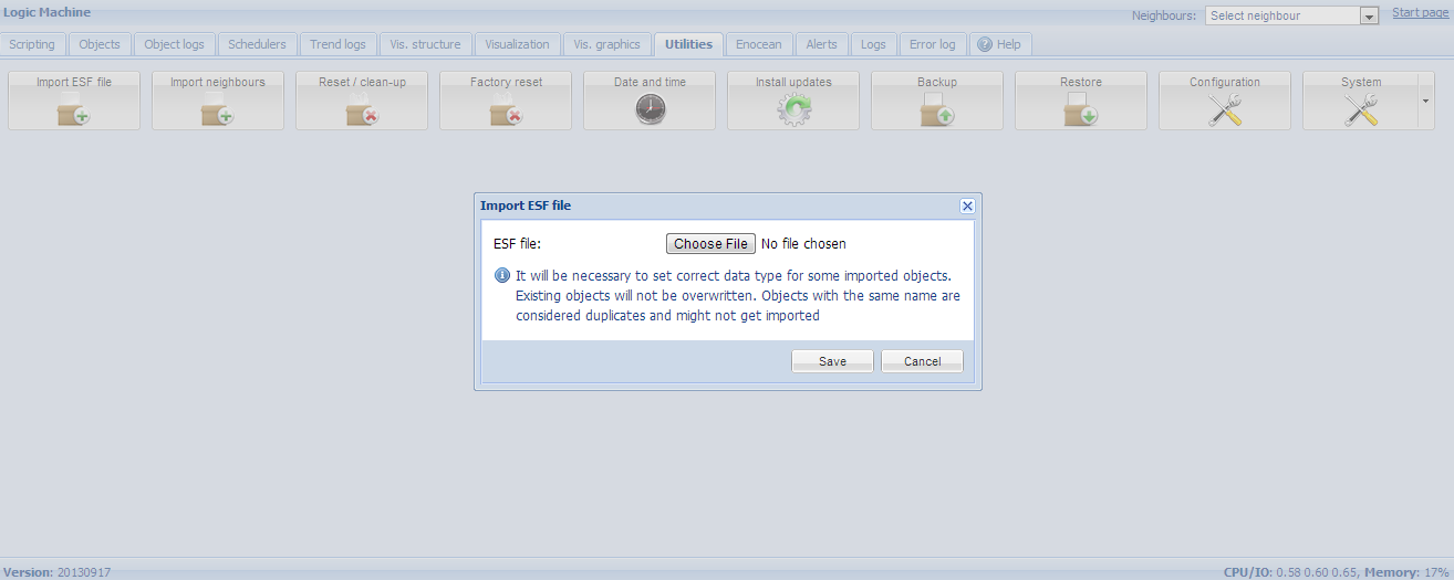
Import objects
-
Fastest way is to import *.ESF file from ETS in Logic Machine –> Utilities –> Import ESF file.
-
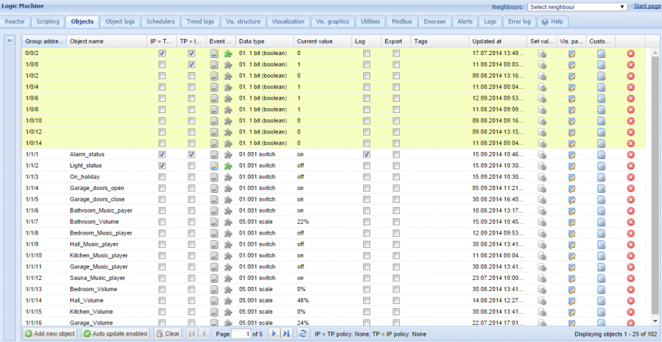
Or connect LM to the bus and it will detect objects automatically (in yellow) in Objects tab once they are activated. Objects can be added manually as well.
Prepare graphics
Either created in Adobe Illustrator or any ready images can be used. In this example we use professionally created designs in Illustrator in SVG form (so we can do scaling depending of the screen size and not loosing the quality)
-
Basic background which can be changed by necessity

-
Foreground which will stay unchanged
-
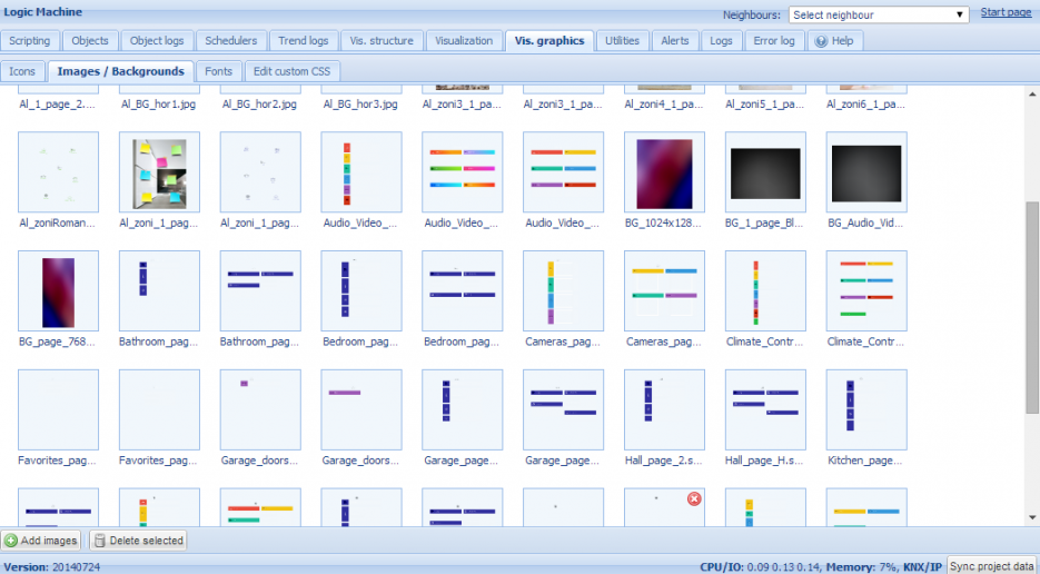
Add both files in Logic Machine –> Vis. Graphics –> Images/Backgrounds
-
Prepare set of icons (preferably in SVG form) and add them in Logic Machine –> Vis. Graphics –> Icons. Or you can use icons predefined in Logic Machine by default.

Create “floor” structure and add objects to the map
-
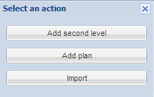
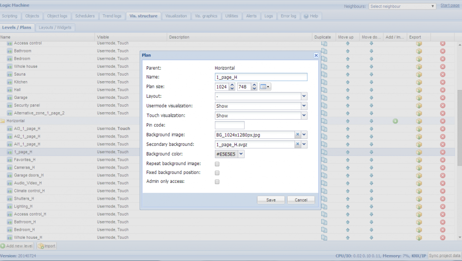
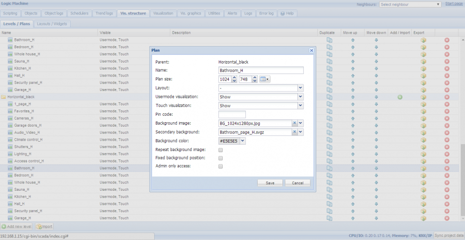
In Logic Machine –> Vis.structure menu the structure of the visualization is defined and visualization backgrounds are uploaded. Use + icon to add floor.
-
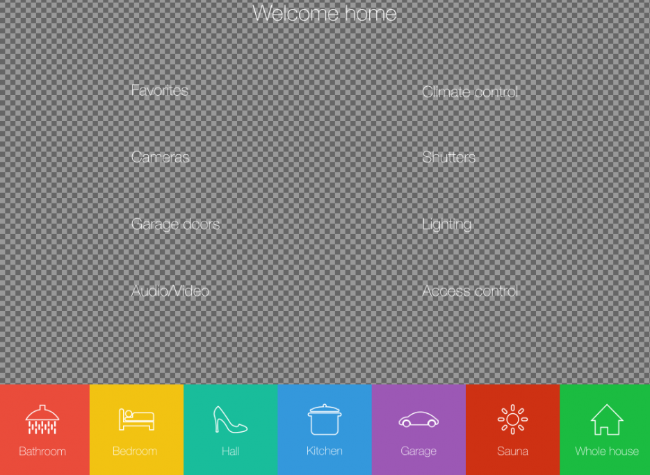
In this example we will create a new floor named “1_page_H” and “Bathroom_H”. First Floor will be a dashboard with link to other rooms and functions. Choose screen resolution for which you are creating this visualization, choose first and second background images from the ones added before.
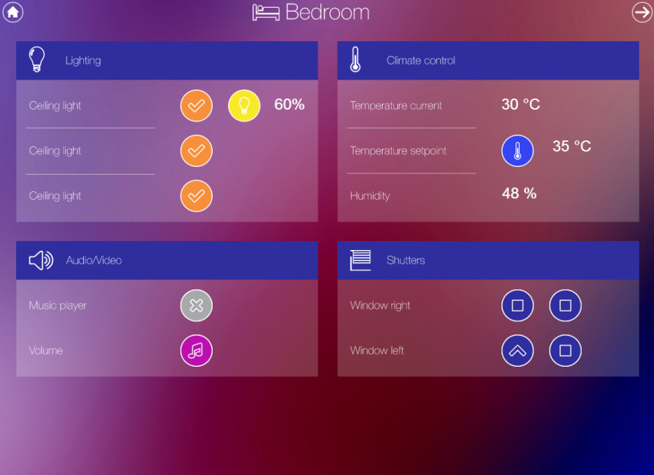
Add objects to newly created visualization map
-
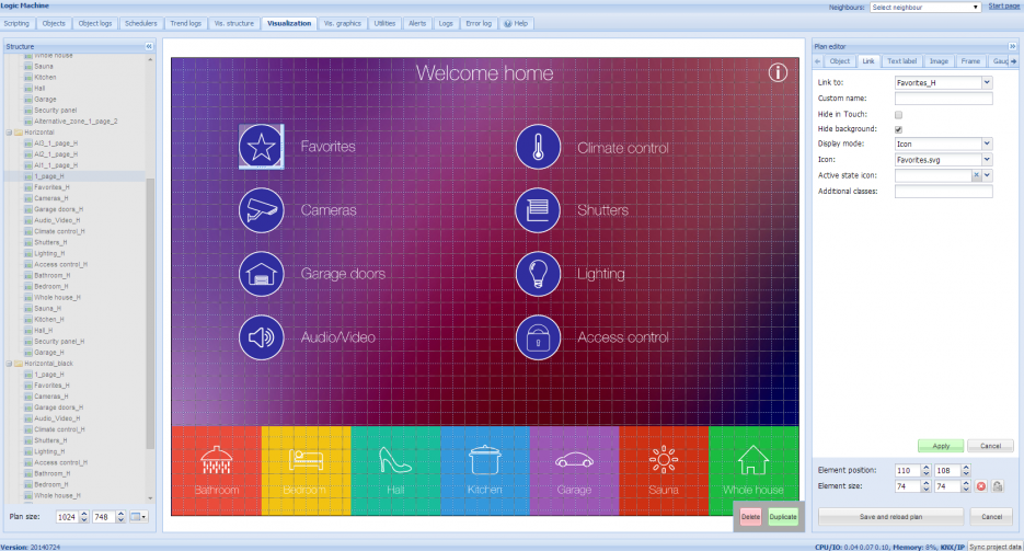
After the building and floor structure is defined, it is visualized in Visualization tab. Controlled and monitored objects can be added and managed in this section. Both side bars can be minimized by pressing on left/right arrow icon making the map more visible especially on small displays.
-
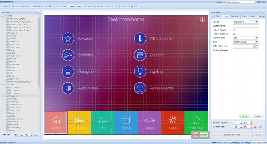
Objects can be added to the map by clicking on Unlock current floor plan for editing button. In this example we are creating first page of visualization which will link to other Floors with specific object control. Add link by clicking on Link tab, choosing specific icon, scale it and place in desired location.
-
This example’s secondary background already contains icons on it, so what is needed, is to add transparent image in Vis.graphics and add this image on top of every icon.
-
When all links are defined, press Save and reload floor plan button.
-
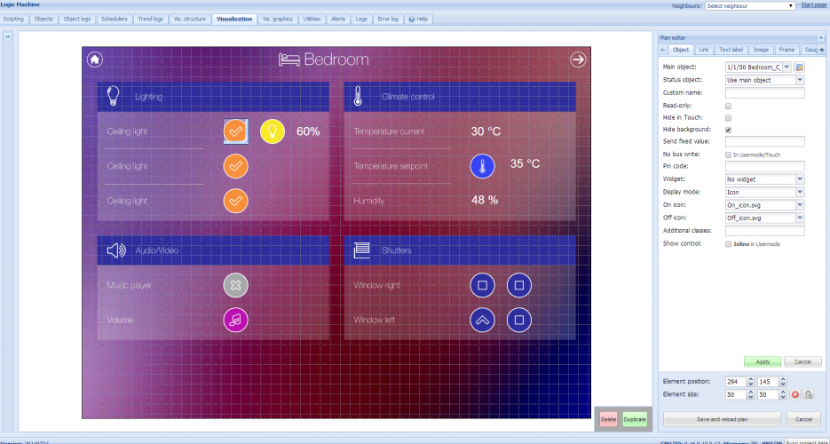
In same way fill the Bedroom plan with object parameters in Object tab.
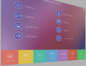
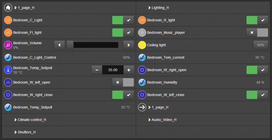
Launching visualization on touch device (iPad in this case)
-
Make sure your iPad is connected wirelessly to the Logic Machine
-
In the browser enter Logic Machine’s IP (default 192.168.0.10)
-
Click on the User mode visualization
-
Save the application as permanent/shortcut in your iPad
-
Touch visualization is also automatically created with list of Floor objects.
-
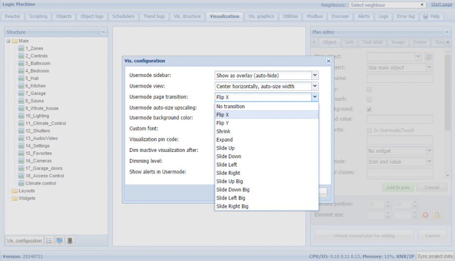
By necessity you can add transitions or Parallax effects to visualization. In this example we will add transition when changing floors, this can be don in Visualization tab by clicking on Vis.configuration button in bottom left corner